Transtorized DIY superhet for the 80m band
For tube devices, it was once common to build amateur radio receivers with old disused radio parts. I wanted to transfer this procedure to a transistor device. The basic idea of the device shown here, developed by myself was thus to build a useful superheterodyne receiver with the expenditure of an FM / MW pocket or clock radio. In the course of this, the parts should be able to be removed predominantly from such devices.
|
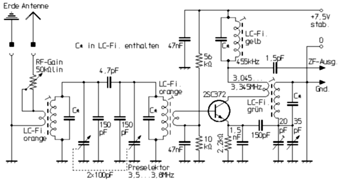
The resulting shortwave receiver has a self-oscillating mixing stage in the input, as opposite shown. It has a similar structure as was long been common in medium wave transistor radios. In contrast, a capacitive voltage division is used instead of the inductive one for the oscillation. As a result, larger capacitances are in parallel, so that the capacitive influences of the transistor which change with the ambient temperature are reduced. |
With a suitable design and careful dimensioning, despite the simple construction, a good frequency stability and a sensitivity that is completely sufficient for the 80-meter band even with shorter antennas could be achieved. But an SSB adequate stability could only be achieved with the shown two-circuit input filtering and loose coupling between the resonant circuits. With a single resonant circuit in the input, the antenna is insufficiently decoupled from the oscillator, so that approaching the antenna results in frequency alterations. The mixer is followed by a two-stage IF amplifier for 455 kHz. As a demodulator serves a circuit how it was otherwise used on its own occasionally as regenerative receiver. A similar, but somewhat more complex arrangement of the demodulator is also found in the previously described Göttinger Baby II. Thus, it is possible with only a single transistor to be able to demodulate either AM or SSB and CW signals. For AM, the fixed feedback is switched off for the device I have designed. With a stronger feedback, the transistor acts as a kind of self-oscillating product detector. For selection of this device, the IF detector hardly contributes. It is achieved primarily by the three single-circuit IF filters. The transformer-less push-pull power amplifier audio amplifier, following on the detector, with has almost no special features.
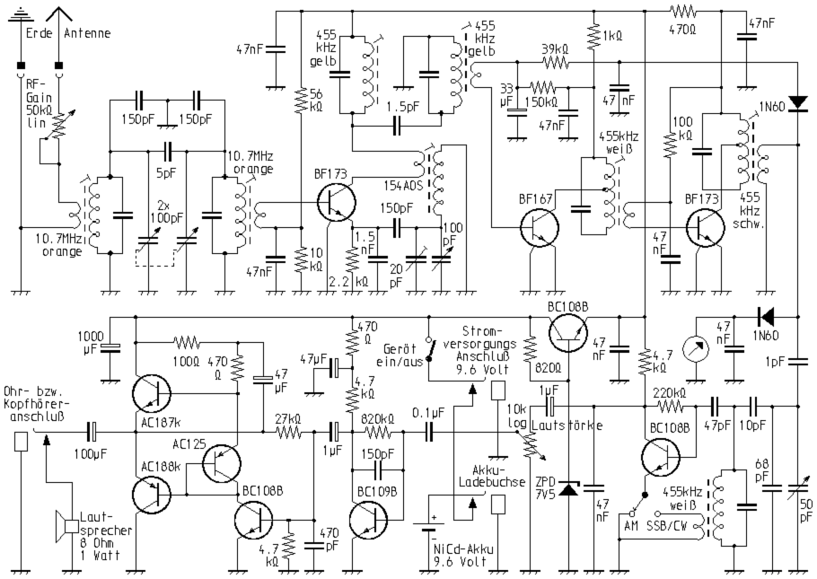
Proper coupling of the self-oscillating product detector to the IF output is quite critical, as it is not only overdriven if the signal is too strong, but also tends to sync. This effect becomes smaller when the BFO frequency, as required for USB or LSB and CW single-character reception, is adjusted to the slope of the IF pass curve. The value of 1 pF indicated in the diagram is to be regarded as a guideline. It is made up of a two-wire strip of computer ribbon cable, which I shortened piece by piece until the cheapest compromise between low-distortion reception and sufficient volume was found.
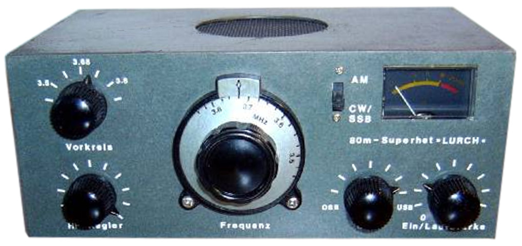
The winding of coils was not necessary for this receiver: the input circuits were made up of 10.7 MHz IF filters for FM broadcast reception, the 455 kHz filters and the demodulator circuit could be obtain from the AM part of old clock radios. For the oscillator circuit i found a suitable coil in my craft box. However, a 10.7 MHz IF filter should also be used here, if the intern capacitor on the bottom side is broken out. The device was installed in a housing made of soldered, copper-coated epoxy boards, which are otherwise used as a base material for the production of printed circuit boards. The housing thus produced was finally painted with enamel paint and labeled with transfer letters. The receiver, despite its simplicity and without the need for any special communication radio components, has surprisingly good reception characteristics. For example, they are not only far superior to those of a simple feedback receiver. Despite the very simple demodulator circuit, a very useful SBB reception is possible. Thus, the reception quality is e.g. also much better, as with simple Superhets with BFO, wich have no product detector. The quality outshines even a Heathkit GR-64 tuned to 80m frequencies, as well as a Koyo KTR-1770.
Extension for the 40m and 20m bands
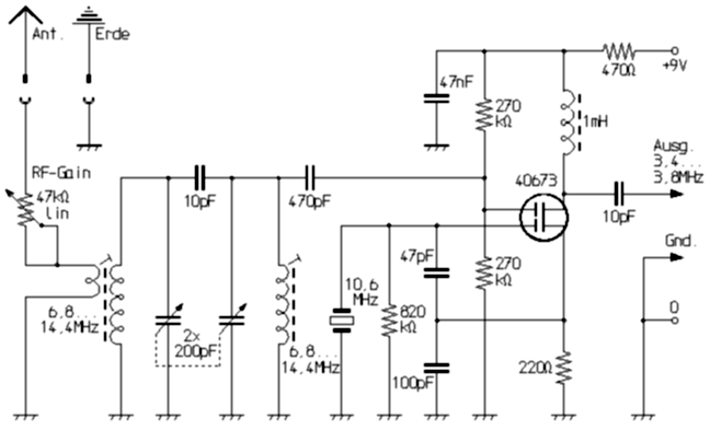
With the simple circuit of a small accessory shown below, I was also able to receive amateur radio stations that transmit in the 40m and 20m band with the device. It is a converter with a dual-gate MOSFET that works as a self-oscillating mixer. I used a 10.595 MHz crystal from an old CB radio. A series trimmer can be used with a series trimmer in the specified circuit to easily pull it up to an oscillation frequency of 10.6 MHz. The 40m band, which was only allowed up to 7.1 MHz at the time, could be received in full in Germany. In the 20m band, however, the range that could be received in this way began at 14.1 MHz, so the telegraph range was not covered. In order to be able to cover the entire 40m and 20m band (6.8 ... 7.2 MHz and 14.0 ... 14.4 MHz), I would had to design the receiver for the range from 3.4 to 3.8 MHz.
|
In this way, an amateur radio receiver for 80m, 40m and 20m could be set up with suitable switches. With the converter switched on, the range selection for 20m / 40m was only made by corresponding adjustment of the 2x200pF variable capacitor. The input sensitivity is quite good thanks to the dual-gate MOSFET used. If a good antenna is used, DX reception in these frequency ranges is not a problem at all. The output of the converter is connected to the high point of the input circuit of the 80m receiver. |
|
Upgraded 80m homemade superhet
The measured on seriously communication and amateur radio receivers modest selectivity of my 80m mini-super can be considerably improved with a ceramic filter insead of the exclusive use of LC circles in the IF part . The types LF-B4 or CFW455IT, which have a bandwidth of approx. 4 kHz, are suitable for this purpose. I was able to achieve an ideal SSB bandwidth and an excellent transfer curve with two 6 kHz ceramic filters connected in series, one for 455 kHz and one for 450 kHz. Contrary to what I suspected (453 kHz - 542 kHz = 1 kHz), the bandwidth is a good 2 kHz with a center frequency of 452.5 kHz. I have not yet investigated whether it is due to the tolerances of the filters used. With a bit too large saddle and a symmetrical transfer curve, a good slope is achieved. This filter combination should also work well for SSB transmitters. The IF part shown below is located in my new 80m mini superhet, in which I incorporated the experience of the first device.
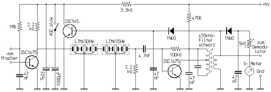
Here I also improved the gain control behavior in the IF section. By an additional control amplifier stage and besides, by this changing the collector voltage of the first IF transistor, a large AGC control range is achieved. With the connection of the 1000μF electrolytic capacitor the AGC can be switched to slow, which is much more pleasant when listening to SSB-circles with partly very strong signals, it gives a better sound impression.
|
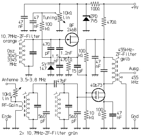
Although the performance of self-oscillating mixers is generally underestimated, they are certainly not the optimum. So in my newer 80m receiver, I use an input part with a dual-gate MOSFET in the mixer and a separate oscillator with a junction FET. Even so, the circuit complexity without the use of integrated circuits remains quite low. The arrangement is extremely sensitive: Already with an approximately 30cm long test cord as an antenna can be received depending on propagation conditions Germany or Europe-wide stronger amateur radio stations. Coupled to a truly antenna, it shows a comparable input sensitivity with commercially available transceivers. As is known, no RF preamp is needed in the 80m range. It would only worsen the mixer overdrive characteristics in the first place. |
As indicated in the schematic, I use again finished IF filters and save me so the work of the coil winding. The two input resonant circuits are more strongly coupled than in the first circuit. Staggered adjustment results in an approximately uniform sensitivity over the entire range, so that the synchronous tuning of the preselection is eliminated.
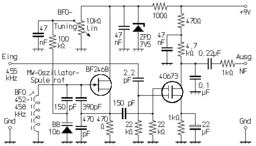
The new device also has a better product detector, which in turn works with a dual-gate MOSFET. The BFO operates as a separate oscillator with a junction FET as in the input circuit.
|
The new receiver, consisting of the shown input part, IF amplifier, product detector and audio amplifier, I have installed in the housing of an old CB mobile device. It provides a very clear reception, even under difficult reception conditions like f.e. the case of contests. The quality is comparable to a number of commercially produced devicesor or can even outperform some. In my opinion the sound is much better, as with a ladder crystal filter. Despite excellent selectivity, it is less sharp, as with many devices and rather comparable to the Drake R4-B in the 2.4 kHz bandwidth setting. |
|