TEVA 5001 FET regenerative receiver for 80-10m
The regeneration receiver presented here also was offered in the 1970s by Technik-Versand in Bremen as a kit. It was intended as a beginner device and allowed the reception of the five amateur radio bands in the 80m, 40m, 20m, 15m and 10m range. The circuit diagram is divided into a regenerative detector with a field effect transistor, a two-stage transistorized audio preamp, the LF power amplifier with an IC and the power supply. The range change takes place in this device by a band switch. As you can see, the range switchover takes up the largest space in the schematic.

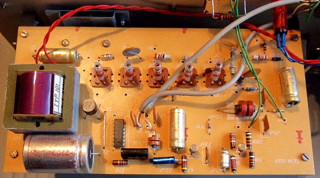
The entire circuit, including the RF coil set and power supply, was built on a printed circuit board, greatly had simplified the wiring and thus the overall design. The fully assembled and mounted board is shown on the next picture. Here, too, shows that the switchable coils for the switchable five wavebands take up quite a lot of space.

The most difficult and time-consuming thing in construction was the work of coil winding. On the immediately shown photo of the bottom of the board, the switch for the band switching can be seen together with its wiring and the tuning rotary capacitor. The latter is a version, as it was formerly used in transistorized AM-FM-Kofferradios. There, the 12pF segments were intended for VHF tuning. The 260pF segments, on the other hand, served as frequency tuning on the center wave. If available, they were of course also used to vote on short and long waves. The Dreko is connected to the front-side control knob via a planetary gear. This allows a sufficiently sensitive adjustment of SSB and CW stations.

The device is in principle well suited for the replica, especially since hardly any special parts are needed. It is also possible to build on a dot board. Instead of the LM380, you'd probably use an LM386 today. It is important in the replica or in your own experiments with such a circuit, the correct polarity of the feedback windings, otherwise no regeneration can come about. Unfortunately, there are no coil data, so they have to be determined experimentally. Experience has shown that the feedback windings should have about 20 to 25% of the number of turns of the coils.
Below, in my opinion, the very appealing exterior of an original device is shown. Many thanks to Joachim Jarling for the giving the photos!
