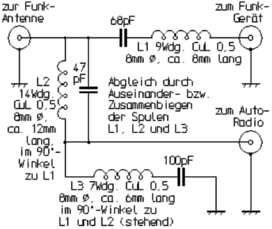
10m-radiotelephony / broadcast antenna splitter
This antenna splitter is suitable for the simultaneous operation of a 10m two-way radio and a broadcast receiver on a common antenna. It consists of absorption and blocking circuits, which are switched so that on the one hand the broadcast receiver is not endangered by the transmission signal and on the other hand, the beside connected input from the two-way radio, does not affect the broadcast reception. Of course you need a special radio antenna to operate the two-way radio. But it must not have a base loading coil, as this would noticeably attenuate FM radio reception. Well suited are radio antennas with center loading coil (CLC antennas) or with a coil in the upper radiator range, as is the case with the DV-27. With this type of antenna, a very favorable length is effective for FM radio reception.
The structure of the antenna splitter is best done in a shielded housing, which can be soldered together from raw material for making boards. The coils are each arranged at a 90 degree angle, or ideally housed in separate shielding chambers created by soldering partitions. The adjustment is made by the coils are pulled apart or compressed. This requires a standing wave meter, a dummy load for 50Ω, an RF relative indicator and a 75Ω resistor. The standing wave meter is inserted into the antenna line to the two-way radio. At the antenna socket of the splitter, the dummy load is connected. First, the coil L1 is matched while the transmitter is switched on until the best standing wave ratio results. The 75 ohm resistor at the broadcast terminal of the antenna splitter must be connected. It simulates the connected radio during the adjustation.

|
At this, only a minimum HF voltage may occur during transmission. This is achieved by trimming the coils L2 and L3 to a minimum pointer deflection on the relative indicator connected there. Since the individual settings influence each other, they should all be repeated several times. Depending on the adjustment, the circuit with the capacitor values specified in the circuit diagram and number of turns for the coils is also suitable for 27 MHz radios. With other dimensioning, it could also be designed for other radio frequencies such as f.e. the 2m or 6m amateur band. Approximately for 0.7 times the number of turns for the coils are about twice as radio frequencies. The capacitors then only need half the values. |