Homemade hybrid guitar amplifier
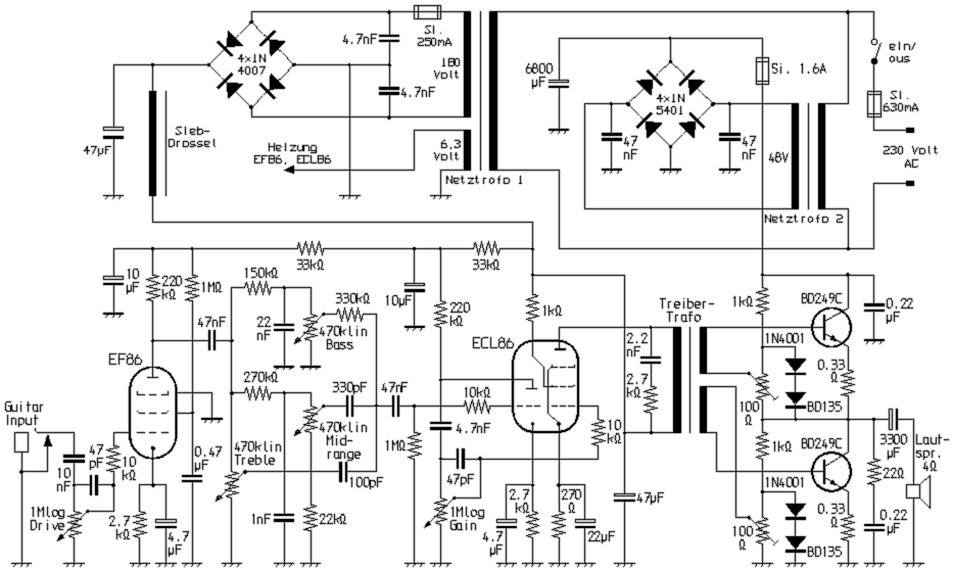
With the circuit presented here can be realized with little effort, a guitar amplifier, which is characterized by virtually unadulterated tube sound and at the same time to deliver a stage-capable output power is able. This is possible because a tube amplifier with an EF86 and an ECL86, which would be suitable as a practice amplifier with about 4 watts of power, drives a single-stage series push-pull amplifier with transistors. In the specified dimensions, this provides over 50 watts RMS. The music performance can reach up to about 100 watts depending on the nature of mains transformer number 2. The four-ohm load can results, for example, from two loudspeakers connected in parallel, each with an impedance of eight ohms. With twelve-inch types can achieved a loud volume. Apart from an improvement in the damping factor, the transistor stage behaves almost neutral in sound. The input stage with a pentode provides a large gain, so that there is enough reserve for slightly or strong distorted, but at that always real tube sounds! With the gain control turned up further, the output stage is more driven. With increasing volume it comes then to a real tube power amp distortion.

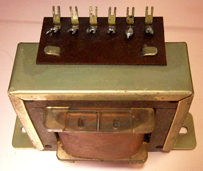
The driver transformer can be obtained by alteration of an output transformer as it shown below. It was from an old tube radio with a single-ended power amplifier for a five-ohm speaker. First, the wires are unsoldered from the terminal block and then removed the headband. The E sheets of the EI core must now be removed from the winding body. Then completely the always external disposed secondary winding can be unwound. Afterwards it is wound up exactly in two halfs again. Does it f.e. consist of out of 120 turns, then 60 turns are wrapped twice. When connecting, it should be noted that these windings drive the two transistors, which incidentally need to be well cooled, in antiphase.

|
The diodes designated BD135 are transistors of this type, which are screwed to the temperature stabilization with the output stage heatsink and of which only the base-emitter diode path is connected. In order to operate the transistor stage without negative feedback sufficiently low distortion, it must be adjusted very accurately. First, set both 100 ohm trimmers so that no bias current flows. Then turn them up alternately piece by piece, until a bias current of up to about 100 milliamps results. The best value for the bias current is if the power amplifier just even does not distort at low levels. For that at the collector of the lower Transisor against ground half voltage must be applied. On this occasion the collector-emitter voltage at both transistors must be the same. Furthermore transistors should be selected to the same current amplification factor! |