Fixed frequency tube receiver for communication radio
Crystal-controlled AM receiver for the 10/11 m range
Many years ago I built a crystal-controlled superhet receiver for the 10m band with ordinary radio or television tubes. It was designed for the AM operating mode. AM amateur stations could often be heard in the range from 28.5 to around 28.7 MHz at the time, which worked with modified CB radios. Depending on the propagation conditions, local traffic rounds, Europe QSOs and sometimes even worldwide radio calls could be heard here. By using CB crystals, the receiver was of course also suitable for listening to the 23 CB radio channels of the time.
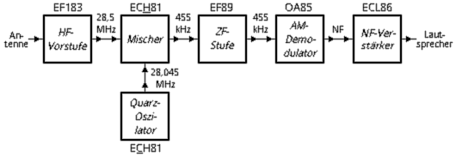
Apart from the used cristal-controlled Pierce oscillator, the receiver was constructed like an ordinary short wave superheterodyne with RF preamplification. The RF preamp used the pentode EF183, a type common was found in the video IF unit of old B/W televisions, was followed by the in the AM part of former broadcast receivers in Germany usual converter circuit with the combined mixer heptode / oscillator triode ECH81. This was followed by an IF amplifier with an EF89, which also had hardly any special features. To keep the effort small, the demodulation was done with a germanium diode.
After essentially not completely unsuccessful experiments with self-wound IF coils, I came up with the idea of using ready-made Japanese IF coils for transistor receivers. My fear that at the demodulator circuit the voltage strength would not be sufficient, was not confirmed. The structure could thus be considerably simplified, especially in mechanical terms. The coils for pre-, intermediate- and oscillator circuit I wound on bobbins from old radio devices. Very well suited to those was disassembled 10.7 MHz IF filter coils from Nordmende tube receivers for broadcast reception.
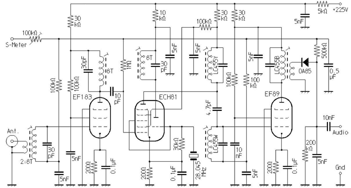
For the then extremely heavily occupied CB area, the IF selection achieved with pure LC filtering was not always sufficient. A ceramic filter of the type LF-B6, which was connected to the coupling windings of the two IF LC-filters between the mixer and the oscillator, remedied this problem. However, some quite large deviations in the oscillation frequency of the parallel resonant Pierce oscillator were to be noticed, because in CB devices, the cristals usually worked in series resonance. Because the CB crystals were not manufactured to uniform specifications, the resulting deviation, due to the better selectivity using the ceramic filter, was more clearly noticeable. Using a series capacitor or coil, depending on the used crystal, was able to adjust to the exact frequency. Amplification and sensitivity of the receiver were comparable to receivers made of commercially available CB radios. A sensitive moving coil meter could be connected directly at the for it designated connection.
- RF coils: 0.8mm enamelled copper wire wound on 8mm bobbins
- LC455Y: IF filter, core color yellow, 455 kHz, 7.5x7.5mm
- LC455W: IF filter, core color white, 455 kHz, 7.5x7.5mm
- LC455B: IF filter, core color black, 455 kHz, 7.5x7.5mm
Crystal-controlled FM receiver for the 2m band
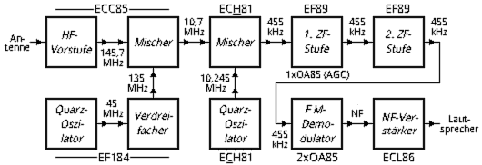
Based on the experience of my 10m tube superhet, I built later in tube technology, a crystal-controlled dual conversion superheterodyne receiver for the 2m band. For the input section I used the double triode ECC85, predominantly found in the VHF part of tube radios. One system worked as a grounded grid RF preamplifier while the other system acted as an additive mixer with grounded cathode. The input section, used for the 10m receiver was thus replaced because it would have produced too much noise in the 2m area. With the ECC85 a usable sensitivity could be achieved. The city repeater, which was a good 10 km away from my former location, could be received with virtually no noise with a simple quarter-wave antenna.
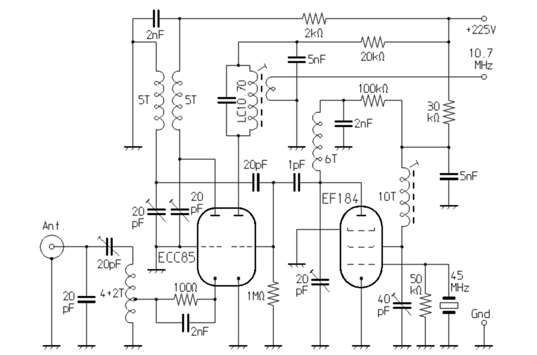
The crystal oscillator worked with an EF184, a type which was also common in the video IF part of old TV sets. In contrast to the EF183 it is not a tube with pronounced AGC properties, but that also was not needed for it. The screen grid of the EF184 acted as an auxiliary anode with which this circuit oscillated as a Pierce oscillator. The resonant circuit at the screen grid was tuned to about 45 MHz, so that corresponding overtone crystals could be used. Such were very common at the time, they were needed among others for the then widespread 2m portable device Trio TR2200. The anode circuit of the EF184 was tuned to the triple frequency, i.e. about 135 MHz, which was fed to the mixer. In this way, the EF184 at the same time could be used as a tripler for the oscillator signal.
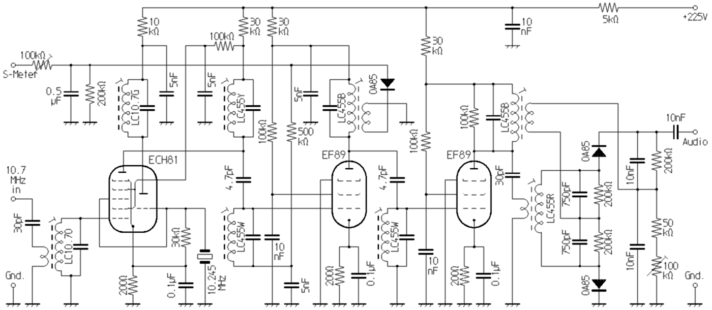
The IF circuit is followed by the IF section with further frequency conversion. The mixing of the first IF from 10.7 MHz to the second IF of 455 kHz was done in the manner already familiar from my 10m superhet with the ECH81. The following first IF amplifier of my dual conversion superhet for 2m had the same structure as in my 10m receiver. This was followed by another IF stage, because of the need for a high boosting, required for FM demodulation. As my first version of an FM demodulator, I used a phase detector realized with a Japanese IF filter and AM oscillator coil. Similar circuits I took over later also for my self-constructed transistor receivers and for the conversion of existing AM receivers for FM. The amplification of this IF part was sufficient to make the input noise on the audio side to a loud empty noise, which more or less disappeared depending on the signal strength with existing carrier. To match it to a tube device, to the IF amplifier I connected a magical eye tube of the type EM84 as the field strength display on my 2m receiver.
- RF coils: air-core coils with a diameter of 8mm made from silver-plated 1mm copper wire
- 45MHz oscillator coil: 0.8mm enamelled copper wire wound on an 8mm bobbin
- LC10.7O: IF filter, core color orange, 10,7 MHz, 7,5x7,5mm
- LC10.7G: IF filter, core color green, 10,7 MHz, 7,5x7,5mm
- LC455Y: IF filter, core color yellow, 455 kHz, 7.5x7.5mm
- LC455W: IF filter, core color white, 455 kHz, 7.5x7.5mm
- LC455B: IF filter, core color black, 455 kHz, 7.5x7.5mm
- LC455R: AM oscillator coil, core color red, 7,5x7,5mm
For the receivers shown suitable audio amplifier
As audio part, I used an amplifier with an ECL86 in standard circuitry for each of my receivers. Suitable output transformers came from Grundig tape recorders of the TK14 and TK17 series. These were soaked versions so that they were spared from corrosion. I have used this arrangement on many of the tube receiver circuits I have tried with good success. With the type ECL86 tube used, an AF output of up to 4 watts can be achieved, depending on the output transformer used. That is enough for strong loudspeaker reception even in noisy surroundings.
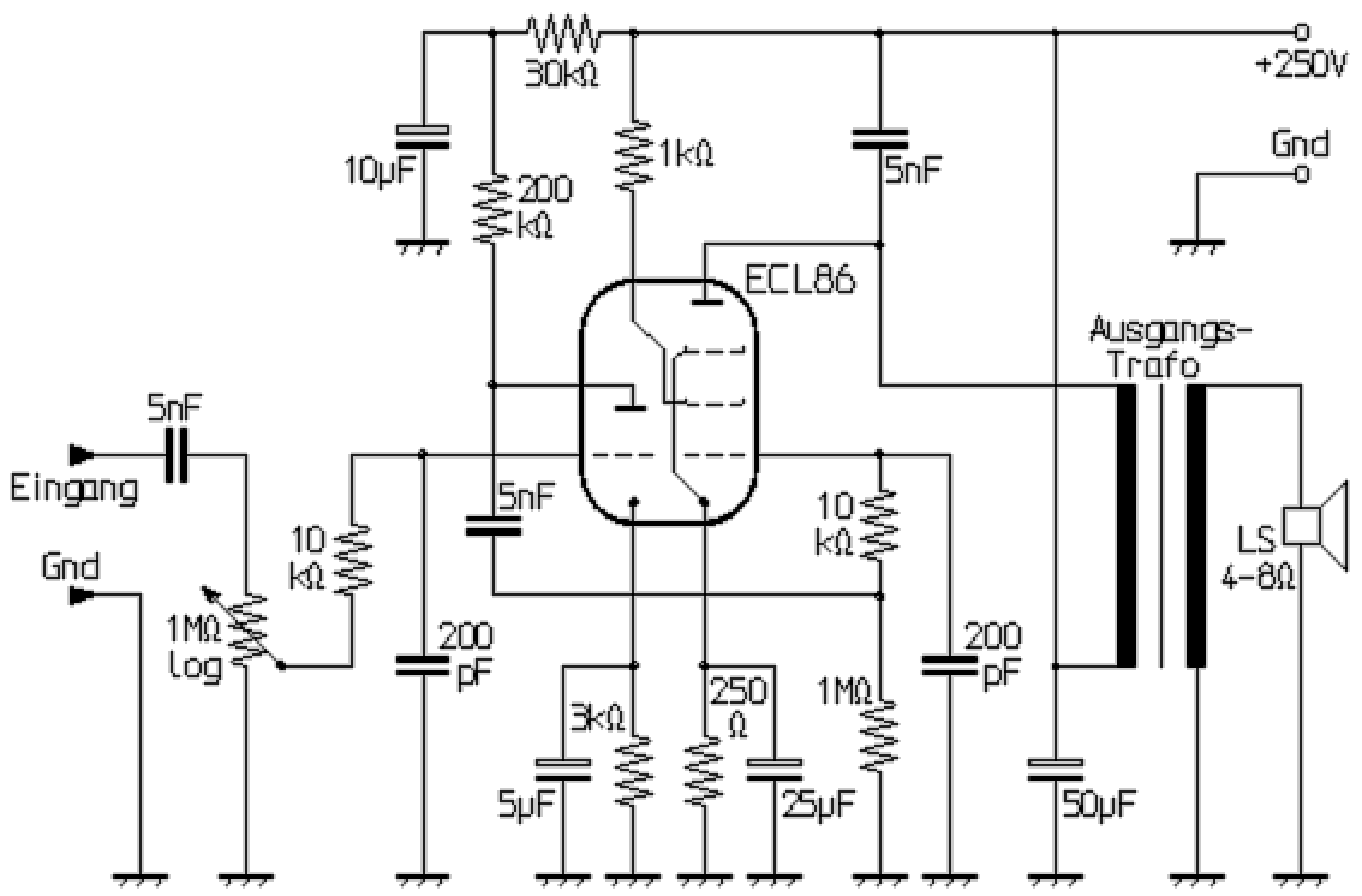
Instead of the ECL86, which has become rare in the meantime, other types of tubes can be used with good success, although some component values then have to be adjusted. For example, the Russian 6F5P tube, which is now very cheap, can also be used. With this type, it is advisable, in the interests of a long service life, not to significantly exceed the anode voltage of 200 volts. The cathode resistance of the pentode should also be increased to 330Ω and the screen grid resistance to 10 kΩ and the grid leakage resistance reduced to 470 kΩ.
If the amplifier is to be used in an AM transceiver, it can of course be used as an AM modulator when transmitting. The best results are achieved with tube transmitters with a special modulation transformer with an additional high-resistance output winding. An anode or combined anode-screen grid modulation can then be used. A normal audio output transformer can also be used with a somewhat lower efficiency if the so-called Heising modulation is used. In this case, the output transformer only serves as a low-frequency choke during transmission and the modulation power is tapped directly at the anode of the audio output tube via an RC parallel combination. Anode modulation is easily possible with smaller transmitters in this way. In the case of more powerful transmitters with outputs of up to 50 watts and more, the screen grid of the HF output tube after all can be modulated in this way with an AF output of 4 watts. The degree of modulation can be increased significantly with the screen grid modulation if modulation is also carried out on the control grid or on the cathode.