Circuit to replace the single crystals
for modify old CB radios to the 10m amateur band
for modify old CB radios to the 10m amateur band
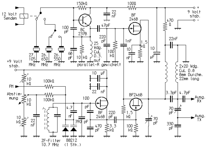
The circuit shown here was originally designed to modify old AM-CB devices with separate channel crystals to transmit and receive, for repeater operation in the 10m band. Later originated on this basis also complete 10m FM homebrew transceiver. For the frequency processing a synthesised VFO is used. For this, the signals of a variable frequency oscillator (e.g., 2.85 ... 3.05 MHz) and a frequency stable crystal oscillator are mixed. Due to the low VFO frequency, the quartz stability is approximately transferred to the filtered mixing product. In this way, frequencies between 29.5 ... 29.7 MHz can be tuned.

The mixer is an asymmetric balanced arrangement in which the crystal signal at the output is already significantly reduced without any selection measures. This arrangement was already used in the legendary Collins transmitters and transceivers - there equipped with triodes.
With a VFO frequency range of 2.55 ... 2.65 furthermore an operating frequency range of 29.0 ... 29.1 MHz is possible. In this area some amateurs experiments with the otherwise forgotten Amplitude Modulation (AM).

The 455 kHz higher injection signal for the receiver (e.g., 29.955 ... 30.155 MHz for FM) is obtained by switching crystals. For FM, it will be important to be able to use a rebuilt in this way device for repeater operation. This can be achieved in a corresponding manner by quartz switching. All required quartz crystals are in their original state in such CB devices, so no special crystals need to be acquired.

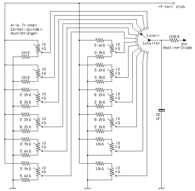
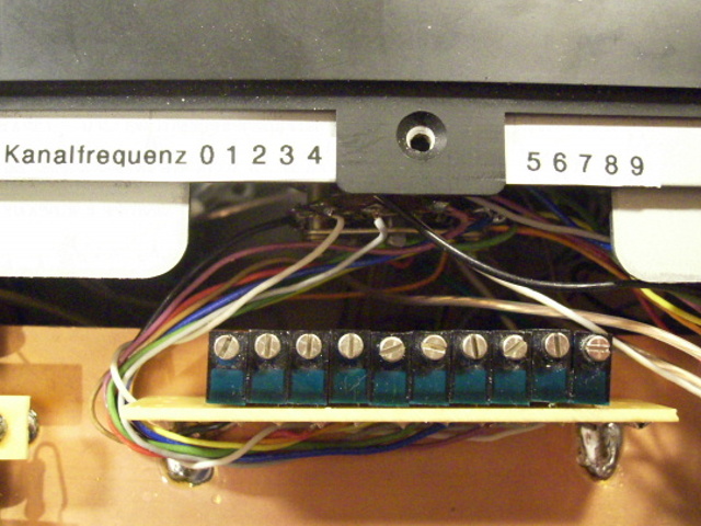
For Tuning, a potentiometer with fine drive is recommended. With suitable design and sufficiently stabilized supply voltage for the VFO, you can also use the original channel switch to choose the frequency. For this purpose, by spindle trimmers pre-adjusted tuning voltages for the desired QRGs are switched.

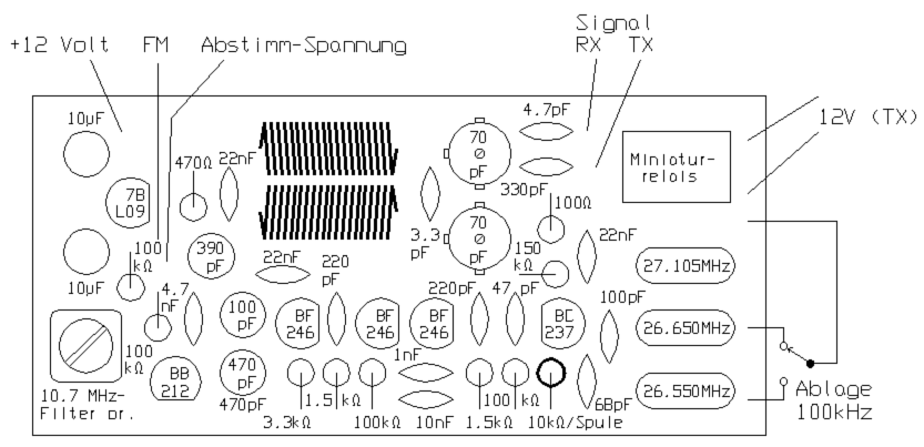
To use the circuit to control an old CB device, the RX output of the described unit is connected to the base of the local oscillator transistor. The crystals of the transmitter and receiver are all pulled out of their sockets or soldered out. The TX output of the circuit is to be connected to the base of the transistor in the transmitter oscillator.