2m-Allmode-Transceiver Semco Terzo
The Semco Terzo is a VFO tunable transceiver for the AM, FM and SSB modes throughout the entire 2m band. It was offered in the early 1970s both as a finished device and as a kit, which is why I introduce it here on my home page. Despite the comparatively small electronic effort, the device works perfectly well. The clear constructed device works with a relatively small number of modules, which was also be purchased individually from the manufacturer. The terminals of these modules are mainly pluggable connected to the wiring, so that their replacement is easily possible by loosening the fastening screws and pulling the cables. The circuit diagrams of these modules are presented below with descriptions. First of all, however, something about the mechanical structure, the controls and the external connections of this interesting and robust device.

The front view shows the S-meter in the upper left corner, which serves as usual at transmit operation the relative display of the RF output signal. Underneath is the 5-pin DIN socket (270°) with a bayonet lock for connecting the microphone. Due to the high-impedance input passive microphones are only usable when it comes as versions with ceramic or crystal capsule, which have an impedance in the order of a few hundred kiloohms. The predominantly widespread dynamic microphones with impedances in the range of a few hundred ohms are unsuitable; the modulation volume remains hereby considerably too small. I successfully use with my Semco Terzo a for CB intended dynamic hand-held microphone with built-in amplifier, where the sensitivity is adjustable with a knurled knob from the outside.
To the right of the S-meter you will find an LED at the top, which signals the transmission mode and next to it a transmit-receive switch, which allows continuous transmissions or operation with microphones without PTT button. Below this is the adjuster knob for the sensitivity of the squelch and again below the volume adjuster knob arranged. The latter is combined with the on / off switch (left stop = off). In the center of the front panel is a large crank button, which is connected via a high-quality fine drive with mutually tensioned gears mechanically with the rotary capacitor of the VFO and the scale for the frequency display.
The first toggle switch in the upper right corner is for exact tuning in to received signals. In order to find the correctly frequency tuning of a possible received station, the receiver hereby is set to zero beat with that station. In SSB operation, this function also serves to calibrate the device so that the transmit and receive frequencies exactly match, this means the device works transceive. Right next to it is the switch for the repeater shift. At the release date of the device, the uniform repeater shift in the 2m band in Germany was still 1.6 MHz. By inserting an additional crystal, however, a second shift could be switched. My device here has an additional crystal for the soon after introduced and used even today 600 kHz shift. The rightmost switch is for switching from simplex to repeater operation as well as for reverse repeater operation. This inter alia allows answers to transmissions in case of failure of the repeater station. In the past, many stations used channel crystal equipped devices, so switching to simplex operation using the repeater input or output frequency often was not readily possible.
Below the beat switch there is a fine-tuning knob and below it one for adjusting the BFO frequency for the frequency-correct SSB reception. When AM or FM operation, they are virtually irrelevant. The red button to the right is used to key the 1750 Hz call tone, which was intended primarily for activating repeater stations. Underneath you will find the mode switch for switching between AM, FM and SSB. For SSB only the operation in the upper sideband is provided, as it is customary in the 2m band and provided according to international agreements.
At the back of the device are the antenna socket (SO-239), the combi power connector (12V DC or 220V AC) and a DIN socket for the speaker connection. In order to avoid mechanical repercussions, the device does not have a built-in loudspeaker. In 12-volt operation, the power transformer uses suitable windings as a converter transformer, which is then connected as a push-pull chopper with two mounted on the rear wall power transistors. My device also has a socket at the rear for connecting a frequency counter. Here an RF signal in the range of 135 to 137 MHz is available depending on the tuned frequency in the range of 144 to 146 MHz. For a frequency-correct display, therefore, an IF offset of 9 MHz must be set on the connected counter. The bulk of the rear is filled by a generously dimensioned ribbed heat sink. The top and bottom are covered with easily demountable perforated plate half shells, so that inside the device for good ventilation is provided.

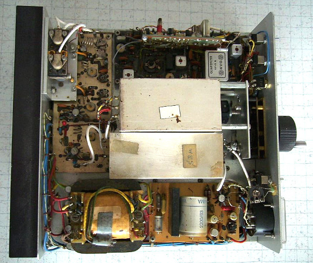
A look inside after removing the upper case shell is shown on the back of the device respectively on the photo on the left, the four-stage HF linear amplifier for transmission mode (Semco designation SLVP). The two pre-stages are operated at a DC voltage of 13.5 volts, driver and power amplifier, however, at the fairly high voltage of 28 volts. The RF PEP output power is 15 watts for FM and 25 watts for AM and SSB. According to the manufacturer, the output transistor is considerably oversized, so that damage by a bad SWR is unlikely. In fact, failures of the final stage assembly are usually related to the fact that the 4.7μF tantalum capacitor connected to the 28V supply has a short circuit, a destruction of the output transistor has hardly become known. The experience with the defective capacitor I have already been allowed to do. Its exchange is relatively easy to accomplish. Even changing the output and driver transistor would, if necessary, be carried out without much effort. For this, however, inter alia, the metal profile with the RF relay for the antenna must be unscrewed, wich in the photo the linear amplifier unit partially hides. The circuit diagram of the linear amplifier is shown below.

To the right of the linear amplifier you can see in the photo the SSB exciter for the transmission mode (Semco designation SAA9.0), which also serves to generate an AM signal. Thus, it provides a modulated AM or SSB signal. Its circuit is shown next. In FM mode, an unmodulated 9 MHz signal is generated here, the modulation occurs in this mode at the VFO. The carrier suppression for SSB via a ring modulator is be affected with a diode quartet, to suppress the unwanted lower sideband a 9-MHz crystal filter XF-9A is used. This was manufactured by the company KVG (Kristallverarbeitung Neckar-Bischofsheim).

Below the SSB exciter, the photo shows the VFO housed in a fully shielded case. It consists of the oscillator in capacitive three-point circuit with feedback from the emitter to the base. The resonant circuit is very loosely coupled. Circuits of this type were often referred to earlier as "Synthetic Rock Oscillator" because of the excellent frequency constancy. The actual oscillator is followed by a buffer stage. It avoids retroactive effects on the oscillator and further vincreases the frequency constancy again. The module provides a adjustable tuning frequency in the range of 18.5 to 20.5 MHz.

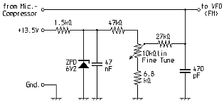
As can be seen on the circuit diagram of the VFO shown above, a fine-tuning circuit by means of a capacitance diode enables FM modulation within this module. When receiving the capacitance diode is used for the receiver fine detuning. The in favor required additional components are housed on a small connection plate with the Semco designation FAP:

Underneath the VFO you will find the transmitter mixer with the Semco designation SBM, which is also placed in a shielding housing. It generates the transmit signal in the range of 144 to 146 MHz from a set signal in the range of 135 to 137 MHz and the output signal of the SSB exciter. It uses a balanced push-pull transistor mixer, which suppresses the input frequencies in the range of 135 to 137 MHz. When using a single-ended mixer, these frequencies would be the strongest in the output spectrum, so that interference of other radio services would be avoided only with the use of considerable filter effort. The image frequencies in the range of 126 to 128 MHz have in the spectrum without filtering, however, only the same strength, as the respective useful signal and have a sufficient frequency spacing, in order to be sufficiently suppressed at relatively low cost of filtering can. As the circuit diagram shows, this is achieved with a single-stage selective amplifier with band-filter coupling. In total, four parallel resonant circuits are involved in this filtering.

Below the transmitter mixer you can see in the photo on the left the mains or converter transformer and on the right the module for the stabilization of the power supply (designation NBSV28S). The series transistors of this unit are mounted on the ribbed heat sink on the back of the device. The circuit, again presented below, is equipped with a permanent short-circuit protection so that e.g. the power amplifier error described above (short circuit in the tantalum capacitor) does not lead to any damage in the power supply unit.


Looking from the bottom into the open device, you can see from the front side on the right side again an assembly, housed in a fully shielded box. Here in the photo you can see it at the bottom. This is the VFO synthesis circuit, referred by Semco as a synthesizer and is provided with the short name SYN. The assembly contains three switchable overtone crystal oscillators, a mixer and a two-stage selective amplifier. Here, the VFO signal and the signal of one of the crystal oscillators are mixed together, so that normally (simplex operation) an adjustable frequency in the range of 135 to 137 MHz arises. In this case, the crystal oscillator is turned on at a frequency of 58.25 MHz. At the collectors of the oscillator transistors, the second harmonic (116.5 MHz) is screened out by means of a bandpass filter and fed to the mixer. By conversion with frequencies in the range of 18.5 to 20.5 MHz from the VFO, the for transmission and reception required injection frequencies arises. With the 57.45-MHz crystal oscillator signals are generated in the same way, but with a shift of 1.6 MHz down, because When the device appeared, this was the standard repeater shift. If the slot for the second switchable slot is equipped with a 57.95 MHz overtone crystal, the today's standard 600 kHz repeater shift is available. As the diagram shows, the crystal oscillators are switched by DC control voltages.

Above the synthesis circuit, the photo shows the converter, so the input module of the receiver. It bears the Semco designation UE9.0. This circuit consists of two RF pre-stages, the second of which is regulated in its gain via the AGC DC voltage supplied by the IF module. The two preamps, both operating with dual-gate MOSFETs, are followed by the mixer equipped with a junction FET. It converts the reception frequencies in the range of 144 to 146 MHz to a fixed first receiver intermediate frequency of 9 MHz.

Above the converter you will find in the picture the all in all most complex assembly, namely the IF module ZFB9.0/3 for the double conversion superhet. Here, the 9MHz IF supplied by the input module is passed through a crystal filter with sufficient bandwidth for FM. After mixing with the 9.455 MHz signal of a crystal oscillator, further selection with ceramic filters on the second IF of 455 kHz is accomplished. By switching these, two bandwidths are available, one of which is sufficiently narrowband for SSB reception. The further IF amplification is essentially done with the integrated circuit TAA981, which actually was developed for IF amplifiers in broadcast receivers. The AM demodulation is done with a diode demodulator, SSB signals are demodulated with a product detector with adjustable BFO. The ZF module provides a DC voltage for the S-meter and has a carefully designed AGC, so a manual control of the receiver is not needed.

At the top left you can see the audio amplifier (Semco designation NFBR) in the picture of the device's bottom view, which input side is via the volume control connected directly to the IF module outputs for AM and SSB. In FM mode, however, the signal comes from the for that designated demodulator, which is housed on a separate board. The output of the audio amplifier leads to the DIN speaker socket on the back of the device. The circuit shows that this module also includes a simple AGC-controlled squelch. This has a very soft onset, which may be the one more and the other might like less. Squelch circuits with such characteristics are also known from CB radios from the AM era. After all, this squelch does not produce any annoying crackles or pops, despite its simplicity.

To the right of the AF amplifier, the already mentioned FM demodulator with the Semco designation SFDK is visible on the photo. It actually is designed with the developed for analog TV sound reception IC TBA120 and has, apart from the LC ratio of the demodulator circuit, no particularities. This was chosen to achieve a good compromise between low signal-to-noise ratio and low distortion for narrowband FM demodulation when properly adjusted.

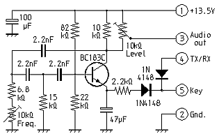
To the right of the FM demodulator you can see the 1750 Hz call tone generator Semco STG in the photo. It is coupled to the transmit-receive switching via diodes, so that at the same time is switched to transmit mode while holding the tone call button, and not at the same time the PTT button on the microphone must be pressed. The circuit shows that the correct pitch and the most favorable modulation depth are separately adjustable by means of trim potentiometers.

In the upper right corner on the photo wich shows the bottom view, you can see right next to the microphone jack the dynamic compressor named Dycom 3. It directly supplies the audio signal required by the SSB exciter, also for AM, and for the connection board FAP for FM. It is designed for rapid down control, so that the transmitter without the else usual Clipper (modulation limiter) provides a clean frequency modulation. As with all other modules here again the circuit diagram:

Apart from the relay plate for transmit-receive switching and the transmitter harmonic filter, all components used in the Semco Terzo has now discussed here. Here are the most important technical data according to the manual of the Semco Terzo:
Frequency range:             144...146 MHz
Operating modes:             AM, FM, SSB, CW
Receiver noise figure:       1,2 dB
Image selection:             abt. 80 dB
Cross modulation strength:   abt. 80 dB
Selectivity AM/SSB:          3 kHz bei -3dB
Selectivity FM:              17 kHz bei -3dB
Audio output power at 4Ω:    2,4 W
TX input power AM/SSB:       45 W PEP
TX output power AM/SSB:      25 W PEP
FM carrier output:           15 W HF
SSB carrier suppression:     50 dB
Sideband suppression:        45 dB
VFO tuning range:            18,5...20,5 MHz
Frequency constance:         abt. 300 Hz / hour
Weight:                      5,7 kg