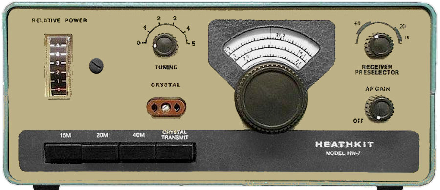
QRP kit transceiver HW-7 from Heathkit
In the mid-1970s came from Heathkit the kit for a simple and compact HF transceiver out, which allowed at least the operation on three bands, but was designed only for telegraphy. A particularity at the time was that a direct conversion receiver was used here. A pure receiver of this type is the here presented by me elsewhere DL0VV receiver, which was developed in the early 1970s. In this receiving principle, the product detector directly operates on the reception frequency, immediate driven by the corresponding tuned VFO, so the selection occurs only on the audio side by means of a low-pass filter. In this way, CW and SSB signals can be received in good quality, but there is no suppression in the range of unwanted sideband. With CW, an interfering signal present there can be tuned to zero-beat, if necessary. Otherwise the experienced telegraphist manages to use his "selective hearing" to identify the other station on the basis of the pitch. At times, when regenerative receivers were the standard device in the amateur radio station, one did so anyway. Incidentally, the Heathkit CW transceivers HW-8 and HW-9, which came out later, did not used a direct conversion receiver anymore. This fact gives the HW-7 to a certain extent a cult status, so that even devices in need of restoration often achieve prices for which one can also get a used five-band SSB transceiver.

The transceiver presented here shows a great similarity to the DL0VV receiver in the input stage. In contrast, the NF filtering here is done with a steep-slope LC low-pass filter. The LF amplifier uses a high reinforcing IC, but on the output side only allows the connection of a headphone. The VFO works for 40m operation in the 80m range, for 20 and 15m in the 40m range. The VFO is followed by a buffer stage followed by a multiplier which brings the signal to the final frequency. For 15m it works as a tripler and otherwise as a doubler. It is striking that throughout the device on a voltage stabilization was omitted, so that the HW-7 must be operated at a fairly stable voltage. Actually, this only works because the audio output stage has a low and as a result of A-mode hardly fluctuating power consumption. When operating directly on a not connected to the electrical system 12V car battery, there are no problems. But it is better to operate the device via an electronically stabilized voltage or at least to retrofit the device with a stabilization for VFO and buffer stage.

There is a transmitter used, which can also be operated with crystal control. In this mode of operation, the circuit of the in this mode two-stage transmitter is a model for numerous homebrew QRP transmitters. But with the HW-7, the transmitter can also be connected to the VFO, which is also used for reception. The device works then as real transceiver, so transmit and receive on equal frequency is feasible. In radio traffic between two such devices, both stations can hear well when working with a frequency offset of a few hundred hertz.
In principle, it is not difficult for a skilled radio tinker to assemble such a transceiver without the kit. Since there are procurement problems for the coil in the audio low-pass and for the AF amplifier IC, I recommend to take over the circuit from the DL0VV receiver at this point. Another difficulty is obtaining a band selector. Apart from the fact that a switch with three switching positions and seven (!) switching levels is needed, not only by that is a normal rotary switch not readily employable. With such a, the distance between the contacts of the various levels is usually quite small, so that retroactive effects can occur between the output and input stages, which do not allow the transmitter to work stably. In contrast, with the pushbutton set of the original device, a sufficient distance between the circuits of the VFO, multiplier, driver and power amplifier stages can be maintained. In a completely self-constructed device, it is a viable option by switching the circuits independently with separate switches. Anyone who is bothered by the increased operating effort, who can also use small relay, which can be placed RF-moderately low. Another option, which is again more operation-intensive but much more flexible, would be the use of plug-in coils. Thus, experiments on other HF bands could be carried out without much effort.

Here are some hints to the contained in the original kit, today quite exotic transistors. Instead of the 40673, a BF981 can easily be used and instead of the MPF105 also FETs of the type 2N3819 do their job. All PNP transistors can be replaced by transistors of type BC328. Instead of the MPS6521 in multiplier and driver stage, works also 2N2222 types. In the output stage, instead of the two MPSU05 connected in parallel, a BD135 can be used, and for the two NPN transistors of the type 2N3393 one uses BC546 or similar.