Retrofitting AM receivers for FM reception

Many older shortwave receivers allow the reception of frequencies up to 30 MHz. A BFO and often even a product detector are mostly present in such devices, so that reception of SSB and CW transmissions is possible (e.g., Kenwood QR-666, Minix MR-73B, Yaesu / Sommerkamp FRG-7, etc.). However, such devices do not have a special FM demodulator. In the upper shortwave range, this mode is now quite common, especially in amateur radio traffic in the 10m band and CB radio. In addition, an FM reception option is advantageous if the device is to be operated with a VHF receive converter. This can be retrofitted into such receivers without major problems. Also, in the manner described below, old AM-CB radios can be modified to FM reception. By additionally changing the CB range to the frequency range over 29, ... MHz and installation of an FM modulator for the transmission mode, you then get a 10m FM amateur radio.
In principle, narrowband FM can also be received with an AM device by detuning the device a bit next to the frequency. However, this so-called slope demodulation has some disadvantages: It can hardly achieve a low-distortion reception, the optimal detuning is dependent on the signal strength and if the field strength is weak one can be glad if anything at all is to be understood. A reception of stations with heavy fadings or the radio traffic of two stations of very different strength is so nearly impossible.
FM detector with the integrated circuit TBA120
In order to obtain optimal reception of FM broadcasts, you thus need a special FM demodulator. It can easily be assembled with just a few components, for which I present here a circuit developed by myself. It has already been successfully put into operation in various receivers.

The prerequisite for the functioning of this extension is that the receiver has an intermediate frequency (the last IF in the case of multi conversion super) in the area around 455 kHz. The IF bandwidth in AM mode is usually sufficient for proper FM demodulation, since very low frequency deviation of up to about 2 kHz are common on the shortwave.
One therefore often speaks of narrow band frequency modulation or NFM (= Narrow Band Frequency Modulation). If the bandwidth of the IF amplifier is too narrow, distortions occur. The remedy is usually the replacement (or switching) of existing crystal or ceramic filters by more broadband versions (for example LF-B8 instead of LF-B6 or CFU455G instead of CFU455H).

The FM demodulator shown here works with a IC of type TBA120. This circuit is already quite old, but still very well available today. It used to be widely used in the audio IF unit (5.5 MHz) of TV sets. In addition, it was also found in the 10.7 MHz IF section of many FM radio receivers. The TBA120S version can be used equally well. Also the Texas-type SN76660 and the ex-DDR types A220D and R220D are suitable. The internal circuitry of these devices essentially includes a multi-stage balanced limiting amplifier and a so-called FM coincidence demodulator which ensures good sound quality. As can be seen from the circuit, only a few additional components are needed.
Construction, assembly and adjustment of the FM demodulator
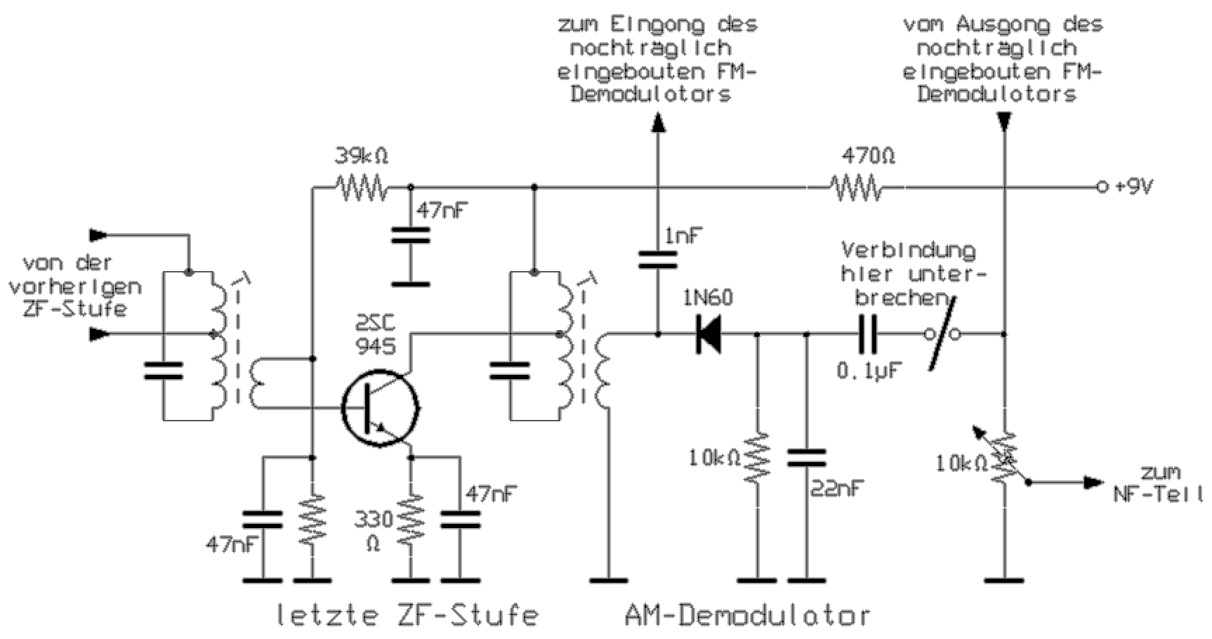
The input of the circuit is connected directly to the IF side wire of the AM demodulator diode. With the value of the 1nF coupling capacitor something may have to be experimented. Too large values can cause oscillations in the IF part of the receiver, too small values will worsen characteristics of limiting, which is usually indicated by too weak noise without signal.

The audio output of the circuit is connected to the mode selector switch so that instead of the AM demodulation signal this signal in the FM position passes to the volume control. Maybe an in the device existing but not absolutely necessary switch can be used for switching, or an additional toggle switch can be installed. In my FRG-7 receiver, I even bothered me to replace the original four-step mode selector with a five-step version.
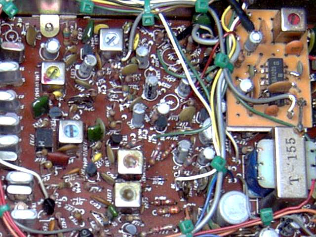
To save the work of coil winding, I have always successfully used coils that can be obtained by slaughtering older clock radios or portable receivers of Far Eastern origin. Such devices are offered at many flea markets for few euros and also contain several other interesting RF components. Suitable here is the oscillator coil used for the AM reception (medium wave). It looks like the well-known Japanese filters, the tuning core is in contrast but usually signed red. If you are not sure: this coil is in the device directly with the variable capacitor connected. One should be careful when removing, and use a desoldering pump.

The adjustation of the presented circuit is very simple: The coil is simply set to the lowest distortion when receiving an NFM station, which usually results in the largest audio volume. Occasionally, careful rejustation of the IF amplifier is advantageous since it is often set to only the maximum gain at the center frequency rather than the optimum transfer curve. In contrast to FM, this namely has a hardly noticeable effect on the AM reception quality.
Ratio detector for 455 kHz for retrofitting a receiver
Some may have a very old AM receiver that they would like to retrofit for FM reception. A demodulator circuit with an IC, such as an the TBA120, can then be felt as a break in style. In addition, it is always very instructive and interesting to dispense with the use of ICs and build circuits entirely from individual components. In this respect, the FM-Demoutator circuit shown here is interesting. It does not quite have as good features as my TBA120 circuit, but it also gives very usable results. It consists of a limiter amplifier with silicium transistors and a downstream ratio detector, as it had been widely used for 10.7 MHz in FM radios for years.

The 10.7 MHz filter coils of FM radio receivers are not usable at 455 kHz. Therefore, a search was made for a way to use other finished coils. In contrast to the usual ratio detectors, the detector coil therefore has no center tap. For this to work, a capacitive division had to be used. This will require two additional resistors. Now, however, an AM oscillator coil (color signed red) from the AM part of an old Japanese radio (for example clock radio) can also be used here. The left coil is obtained from a 455 kHz IF filter (color signed black), as found in most old CB radios and many AM broadcast receivers at the output of the last IF stage. But here, the built-in resonant circuit capacitor is broken out at the bottom.


The adjustment of this circuit is somewhat more complicated than in IC circuits with only one resonant circuit, since two coils must be set here. The left coil is set to maximum noise without signal, the right coil again to low-distortion, loud reception. This procedure should preferably be repeated several times. An adjustment of the IF amplifier can of course still bring improvement here. The next photo shows the assembly from the solder side.