Do-it-yourself regenerative FET receivers for SW
Based on my experiences with some replicas of the RIM Trabant KM, I undertook various attempts to solve the specific problems of regenerative receiver circuits with bipolar transistor. Those arrangements, however, became much more complicated and less reproducible without really effecting any significant improvements. For example, I have tried with moderate success to reduce the damping of the resonant circuit by using a darlington configuration, or to minimize synchronization effects by using separate transistors for demodulation and regeneration. But then I tried field-effect transistors and was very surprised by the success. The results achieved came very close to those of tube circuits.

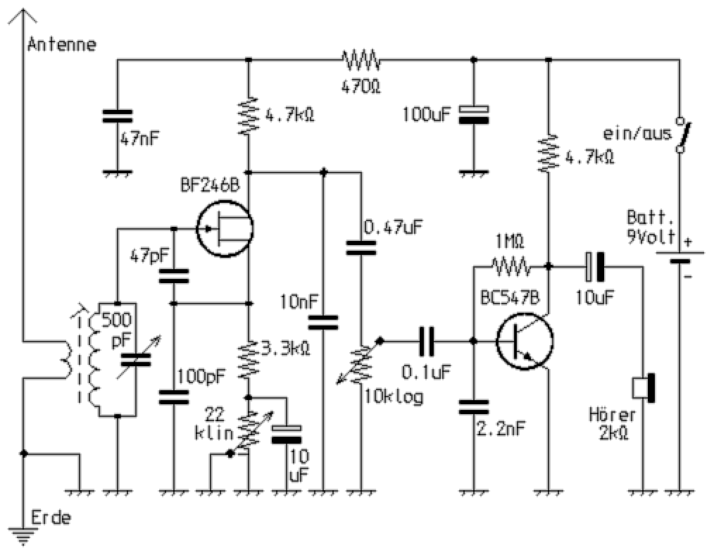
Since I always feel it interesting to find the simplest usable variant for circuit types, I came to a solution with a regenerative detector using a FET, followed by an audio amplification stage, how presented with this schematic. The circuit with the FET offered much greater gain and less overdrive phenomena at the same time better selectivity. Synchronization effects only occurred at very strong signal strengths. Consequently, even with the single-stage transistor amplifier, a sufficiently loud headphone reception of amateur radio stations could be achieved.

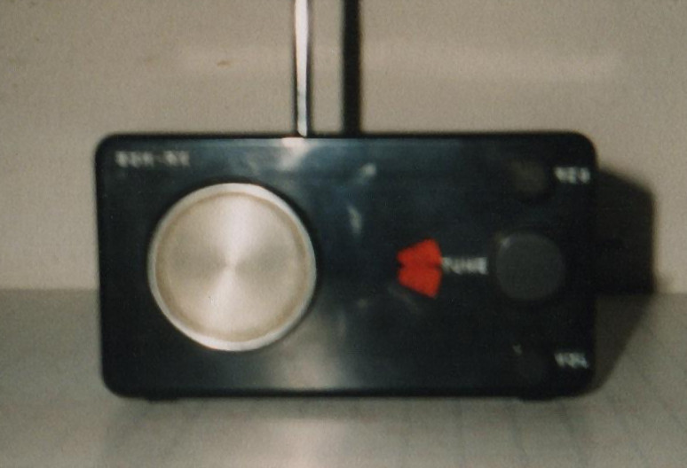
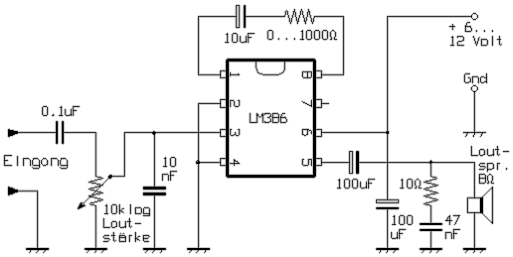
I built such a device, designed as a monoband receiver for the 80m band, in a plastic housing. To enable speaker reception, I later replaced the single-stage audio amplifier by a circuit with the LM386. Despite the very simple circuit, the device offered a very usable reception of amateur radio transmissions in the operating modes SSB and CW. The feedback oscillation had soft onset, so that always the best setting could be found without effort.

With the resistor in series with the 10µF capacitor, the amplification of the audio signal can be determined. For the maximum gain factor of about 200, its value can also be zero ohms. In this case, only the electrolytic capacitor is connected between pin 1 and pin 8. Depending on the wiring, with such a high amplification, especially with higher volume settings, the receiver can generate low-frequency natural oscillations. This would be noticeable through strong interfering noises such as whirring or squeaking. When using a loudspeaker with particularly good efficiency, the RC combination or the 10µF capacitor can also be omitted entirely. In this case, the audio gain falls to about 20, whereby particularly stable operation is guaranteed. The gain could also be adjusted with a 1kΩ trimmer in series.
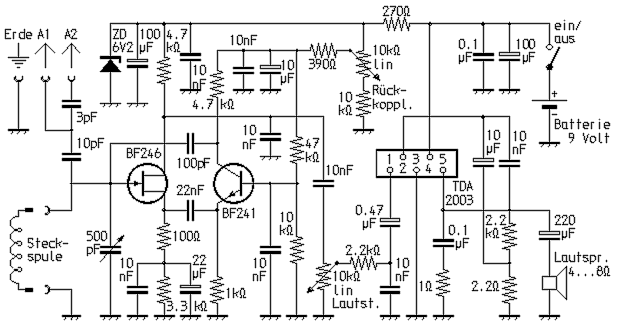
The device constructed in this way offered a very useful reception of amateur radio broadcasts in the operating modes SSB and CW despite the extremely simple circuit. The regeneration feedback started softly, so that the best setting could always be found without any effort. Encouraged by these good reception results, I continued experimenting and came up with the circuit of an very well-functioning feedback receiver, in which the FET only serves as a demodulator. The amplification required for feedback or undamping is provided by an additional bipolar transistor (BJT). As a result of this arrangement, the resonant circuit coil, as with the RIM Trabant KM, requires neither taps nor any coupling coils. But in comparison, the reception properties are considerably better with this arrangement. To improve the frequency stability, the receiver received voltage stabilization by means of a Zener diode.

The plug-in coils, which were initially used for range switching, were later replaced by a set of coils with a rotary switch. The large value of the capacitor between the source of the FET and the emitter of the BJT resulted in order to be able to make the circuit oscillate even in the long-wave range. A continuous reception range of around 160 kHz to 30 MHz could be covered over five switchable wavebands. In order to be sensitive able to fine-tune SSB and telegraph stations, I switched a capacitance diode tuning parallel to the variable capacitor. This fine adjustment concurrently was later used to tune an additional VHF receiver with the IC TDA7000. The fine adjustment of the RF circuit also enabled a sufficiently precise adjustment in the upper frequency range in order to be able to demodulate 10m amateur radio and CB stations on the flank, wich using narrowband frequency modulation. The IC of the type TDA2003 used here in the audio part was intended to ensure that the device was also usable for radio reception. For this it is namely advisable to design the audio output a little more generously.