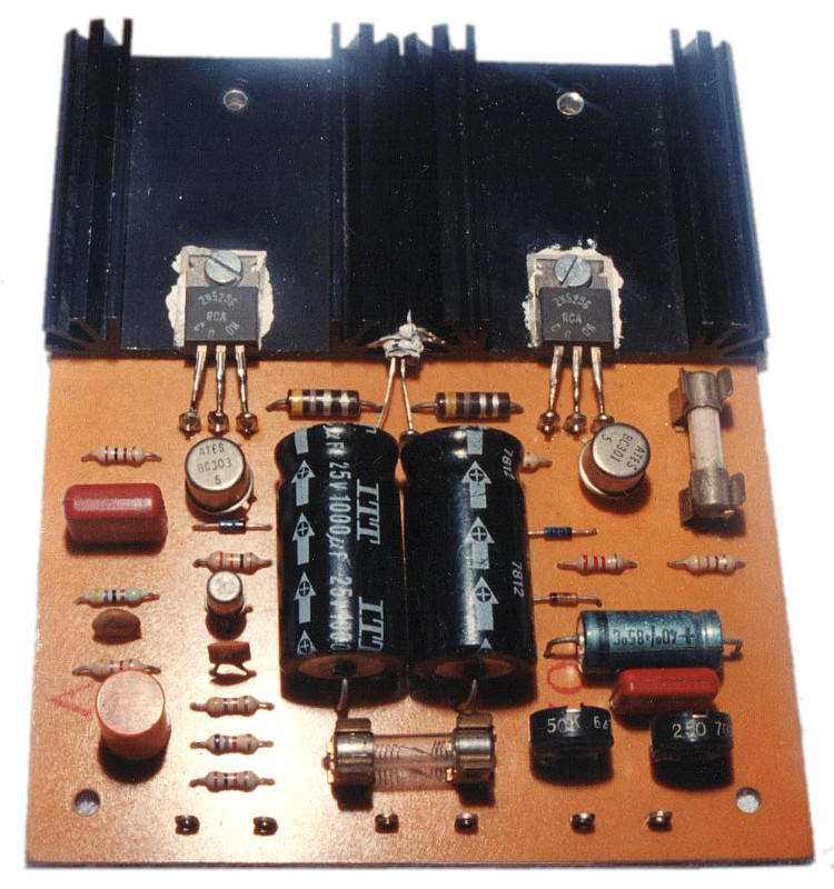
Transformerless Quasi-complementary 15 watt power amp
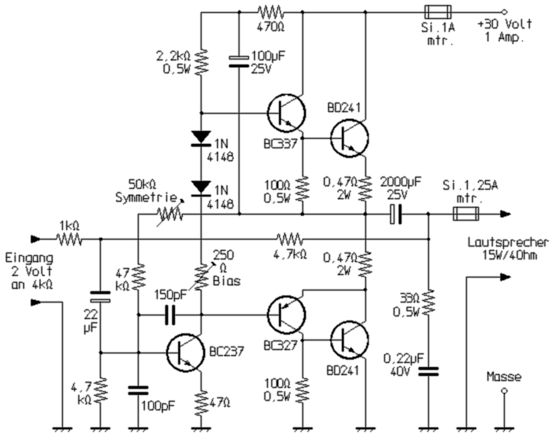
This classic amongst the transformerless audio power amplifiers among others is suitable for smaller music systems, karaoke amplifiers or for guitar practice amplifiers. For stereo applications, of course, two such units are required. The circuit operates with a quasi-complementary output stage, so that two identical output stage transistors (here BD241) can be used. All stages are DC coupled. Complementary driver transistors (BC327 and BC337) are required for the antiphase activation of the final transistors. Previously, silicon PNP type power transistors were very expensive, and the available power transisers had only small current gain factors well below 100, making this arrangement the best compromise of low construction cost, low circuit efford, good frequency range and low distortion. The requirements of the hifi standard DIN 45500 could thus just be met.


The entire voltage gain is provided by the pre-amp transistor (BC237), all other transistors act as pure current amplifiers. A bootstrap circuit (470Ω, 100μF) increases the headroom of the pre-stage. The symmetry is set with the 50kΩ trimmer. When set correctly, the voltage at the positive pole of the output electrolytic capacitor (2000μF) is exactly half the value of the supply voltage. This achieves maximum controllability and therefore the highest output power. Since only one small open-loop gain is achieved with the one pre-amp stage, with the 47Ω emitter resistor and the 4.7kΩ resistor it has a double negative feedback from the output to the input to reduce the distortion factor. In order to keep the distortion small, the driver and output stage transistors must also be selected for as equal as possible current gain factors. In addition, with the 250Ω trimmer a sufficient power amp bias current must be set. It is adjusted so that when there is a weak input signal (i.e. at low volume) the current transfer distortions of the output stage transistors just disappear. For temperature stabilization of the bias current, the diodes must be mounted on the output stage heat sink for thermal coupling.
In principle, the circuit with stronger driver and end transistors at higher supply voltage would be suitable for higher power. With a view to a small harmonic distortion and the then required even larger input signal, a circuit with a further stage for voltage amplification is much better suited for this purpose.