Treble and fuzz booster with germanium transistors
Originally, electric guitars were used to achieve a greater volume, as with their purely acoustic representatives. With their presence, in large halls the entire audience could now also be reached. In jazz combos it again had been also always a problem that the guitar usually could not prevail sufficiently against the other instruments, which were inherently louder. In particular, the brass instruments and the drums often gave the guitarist little chances of to assert oneself in terms of volume. In addition, it was now possible to use the guitar as a real melody instrument. This possibility was used for melody improvisations, especially in jazz music, from around the 1940s.
With the rapid spread of transistors since the early 1960s, this technology found its way into music electronics from around the mid-1960s. Transistors were initially still very expensive and first by no means suitable for the high power required for guitar amplifiers. In the second half of the 1960s, however, transistorized accessories in particular enjoyed increasing popularity, which were intended to be inserted between the instrument and amplifier in order to expand the variety of sounds offered by the electric guitar. For the first time, it was no longer a matter of only increasing the volume, but of enabling new forms of expression through sound effects. These almost always battery-operated devices were basically only one or two-stage amplifiers, which alienated the sound of the guitar by overdriving or overemphasizing a frequency range. In accordance with the state of the art at the time, these devices initially worked entirely with germanium transistors.
The treble booster: Brilliant sound with a slight distortion
For the first time, a so-called treble booster was produced by the English company Dallas Musical Ltd. and presented under the model name Rangemaster. By the end of the 1960s, such or similar devices were then already being offered by many various manufacturers. Also Japanese manufacturers had now increasingly conquering the market here. When, at the beginning of the 1970s, transistors were now available for hobby electronics engineers at affordable prices, corresponding switching suggestions also appeared in electronics magazines. I have built such circuits several times over the years, tested them extensively and tried to improve them. In the end, however, I always ended up with the circuit shown here, which largely corresponds to the one that was used in the Rangemaster.

This circuit is basically a preamplifier, which, due to the small coupling capacities at the input and output, causes a considerable increase in treble or a disadvantage for the low tones. Inserted between the guitar and the amplifier, there is an overdrive and consequently a high proportion of overtones. Although the guitar now sounds very distorted, chords can be heard clearly and precisely. This is because the overtones in particular are affected by the distortion and so even more overtones are formed. The basic tones, on the other hand, are less overdriven and are very present in the sound image. Since most of the non-linear distortion is caused by overdriving in the preamp of the guitar amplifier as a result of the additional gain of the treble booster, this works best with tube amplifiers. The degree of additional distortion is set with the 10kΩ potentiometer. All other settings can be made as usual on the amp and the guitar.
While I'm a fan of conventionally wired circuits, I specifically disagree with "esoteric" claims that a hand-wired treble booster sounds better. This cannot be proven physically or metrologically. Remember that, in contrast to tube circuits, the input and output resistance of this circuit are only a few kilo-ohms. Noteworthy shunts due to insufficient insulation of a circuit board are therefore completely excluded. Also, with such low impedances, capacitive couplings through the line routing are definitely not to be feared in the LF area. However, with such a simple circuit there is nothing to prevent the device from being constructed with conventional wiring and without a circuit board.
In contrast to the type OC44 or OC71 transistor used in the original device, I use a type AC151R transistor. In terms of sound, it hardly makes an audible difference, but when using the original types, the associated strong inherent noise of the circuit bothers me. The AC151R was developed for use in preamplifiers with high input sensitivity, for example for magnetic record pickup systems or microphone preamplifiers, and is one of the lowest-noise AF types from the germanium era. Despite the availability of significantly lower-noise types, the use of silicon transistors is not recommended. There is a clear loss of the vintage sound here due to the characteristic curves that differ significantly from the original transistors.

Extremely distorted and overtone-rich sound with the fuzz booster
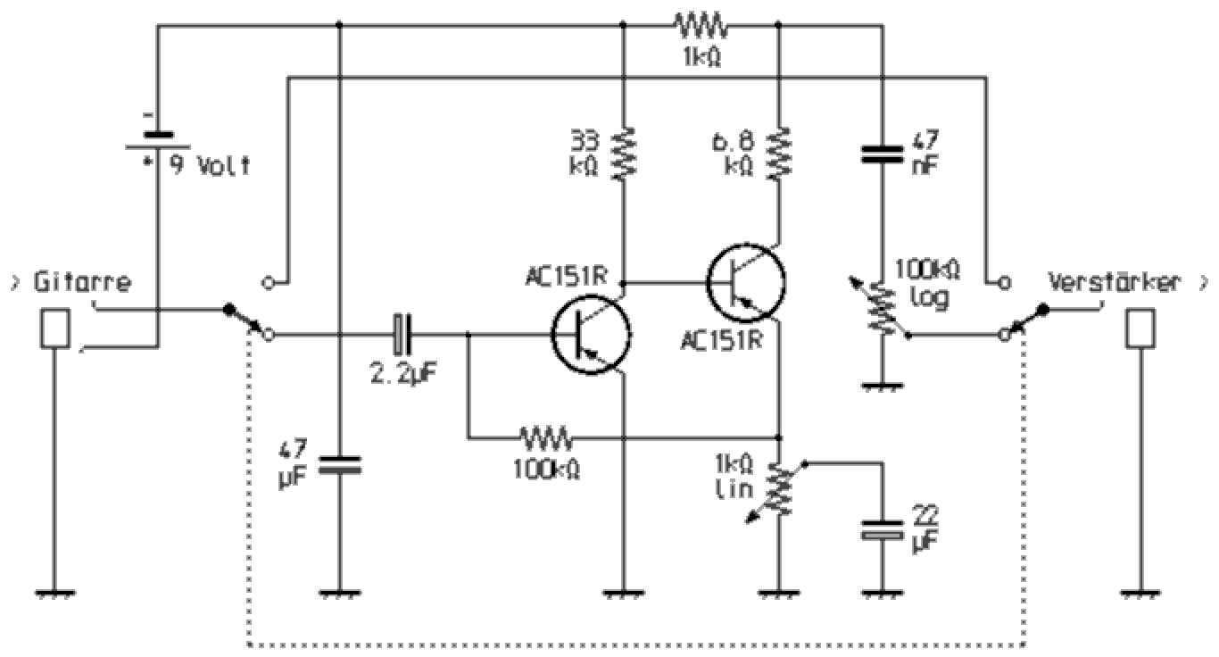
The fuzz booster was at least as widespread as the treble booster. This is a two-stage galvanically coupled amplifier. The circuit has a stable operating point that is largely independent of the ambient temperature due to negative DC feedback. That basic circuit was very common for microphone preamps, among other things. I assume that its use as a guitar distortion device came about because a guitarist and tinkerer connected his instrument to the microphone input of a transistorized vocal amplifier system and found the sound result interesting ...

The shown circuit of a fuzz booster, which I also built several times, generates an extremely overdriven sound that is rich in overtones, depending on the setting. For reasons, as explained with the Treble Booster, I have also decided to use the low-noise germanium transistors of the AC151R type here. This choice is particularly recommended for the transistor on the input side. With regard to the overtone distribution, the sound character of the guitar connected via the fuzz booster is sometimes reminiscent to that of a trumpet. The degree of distortion can be influenced by the 1kΩ potentiometer by completely short-circuiting the negative feedback for the signal alternating voltage via the 22µF electrolytic capacitor at the maximum setting and thus completely eliminating it. With the minimum setting, however, the signal is fed back more strongly. Although the distortion can be reduced with this potentiometer, the circuit is unsuitable for slightly distorted "crunch" sounds. One reason is that with this arrangement it is not possible to achieve a soft overdrive. In addition, all frequency components are equally overdriven. Beside that to the formation of overtones, there is consequently strong intermodulation, which means that when chords are played, a large number of inharmonic frequencies are formed and the individual tones involved in the chord can therefore hardly be heard. The device is therefore particularly suitable for lead guitar playing and special effects as well as, if necessary, for aggressive rhythm sounds with power chords.
A combination device consisting of a treble and fuzz booster
With both effects, the effect can be switched off by means of "bypass" using a two-pole switch. The guitar signal is then routed past the circuit and remains completely unaffected. There is no need for an on / off switch if a stereo jack socket is used on the input side. The positive pole of the battery (here ground!) Is connected to the channel of the stereo socket, which is connected to the plug shaft when the mono plug is inserted. The power is on when the guitar cable is connected. If the plug is pulled out, the device is switched off.

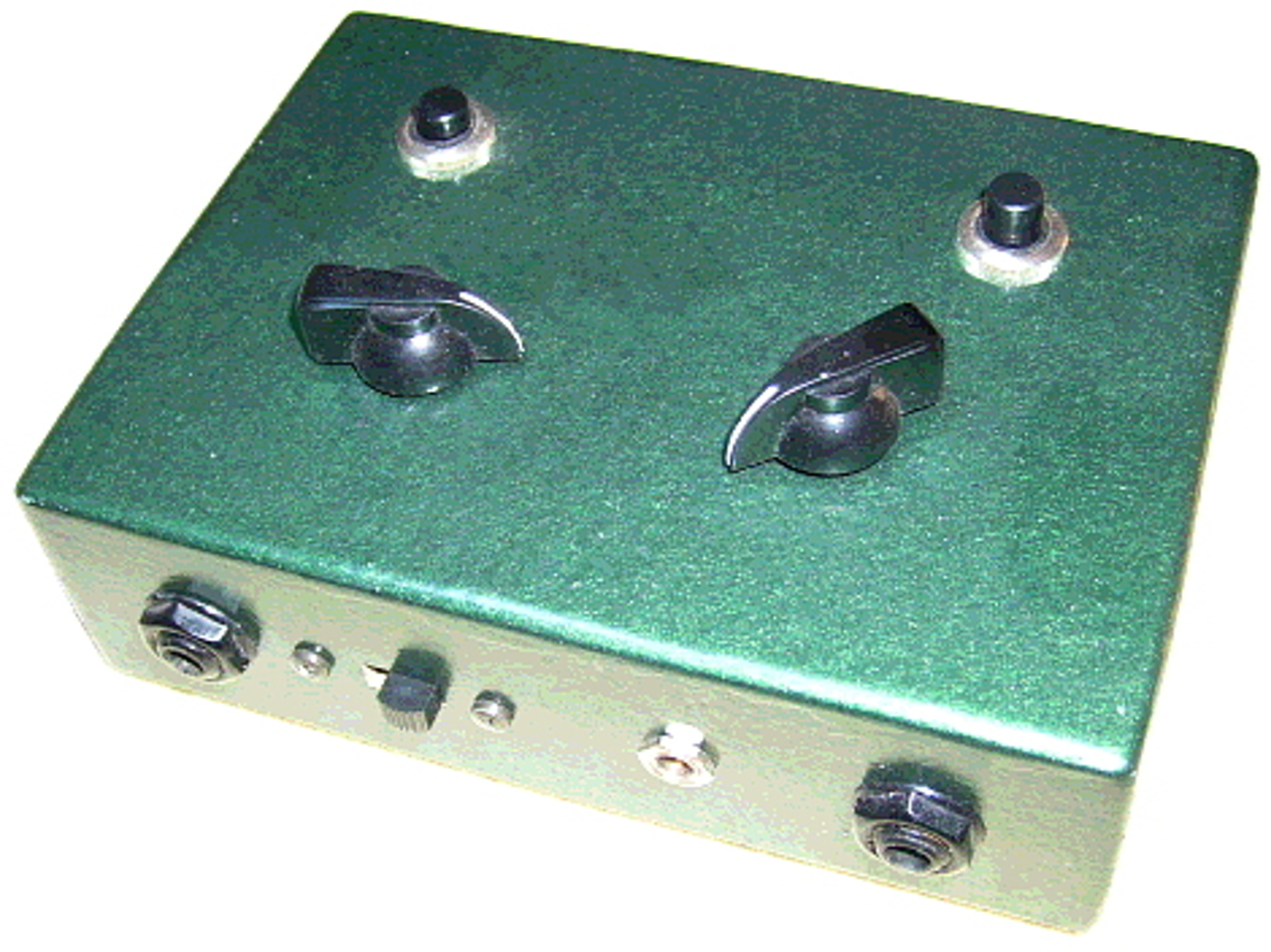
Finally, I installed both effects as a combination device in the housing shown. In the sequence, the treble booster is arranged in front of the fuzz booster in terms of circuitry. Both effects can be switched on and off independently of one another via bypass. The housing in vintage design was created by glued together hardboard, in which the connection points are reinforced by thin rectangular wood rods. These can be obtained as recycling items by collecting burned out firework rockets. The edges of the case were first carefully rounded off with a belt sander and then with a file. After varnishing with hammer finish effect paint, the whole thing looks very metallic. The vintage look is supported by the chicken head buttons used. To shield against interference fields, the inside of the housing is lined with metallic adhesive film over the entire surface. That is electrically connected to the positive pole of the battery. The slide switch is used to switch to operation from an external power supply.